
Assembly Instructions and Adjustments
Included Parts:
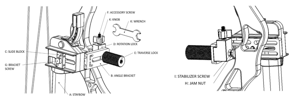
A: (1) STAYBOW
B: (1) ANGLE BRACKET
C: (1) SLIDE BLOCK
D: (1) ROTATION LOCK
E: (1) TRAVERSE LOCK
F: (1) ACCESORY SCREW
G: (1) BRACKET SCREW
H: (2) JAM NUT
I: (1) STABILIZER SCREW
J: (1) WRENCH
K: (1) KNOB
Assembly Instructions: Compound Bow
Step 1:
Screw the preassembled (D) ROTATION LOCK, (I) STABILIZER SCREW and (H) JAM NUTs into your stabilizer mount until the (I) STABILIZER SCREW bottoms out.
Step 2:
For right-handed users, position the (B) ANGLE BRACKET in the pocket on the left side of the (A) STAYBOW upper housing, with the bracket facing out to the left. For left-handed users, position the (B) ANGLE BRACKET in the pocket on the right side of the (A) STAYBOW upper housing, with the bracket facing out to the right.
Step 3:
Insert the (G) BRACKET SCREW through the (C) SLIDE BLOCK, through the slot in the (A) STAYBOW upper housing and loosely thread it into the tap on the (B) ANGLE BRACKET.
Step 3:
Step 4:
Position the assembled (A) STAYBOW and (B) ANGLE BRACKET onto the (D) ROTATION LOCK by sliding the (D) ROTATION LOCK into the groove of the (B) ANGLE BRACKET.
Step 5:
Loosely thread the (E) TRAVERSE LOCK into the (D) ROTATION LOCK.
Adjustments: Compound Bows
Step 1:
Ensure your bow and the (A) STAYBOW are parallel to each other and tighten the (H) JAM NUT securely against your stabilizer mount.
Step 2:
While holding your bow in the normal firing position (no need to draw your bow) pull the (A) STAYBOW trigger to allow the leg to fall to the ground. Release the trigger to allow the leg to lock into position.
Step 3:
Position the trigger so your fingers comfortably reach, by sliding the (D) ROTATION LOCK left or right in the (B) ANGLE BRACKET and sliding the (B) ANGLE BRACKET forward or back in the (A) STAYBOW upper housing before tightening the (E) TRAVERSE LOCK and (G) BRACKET SCREW securely.
Assembly Instructions: Accessories (Camera, Gun Rest, Lighting, Speaker Etc.) (Not included)
Step 1:
Position the (B) ANGLE BRACKET in the pocket on either side of the (A) STAYBOW upper housing.
Step 2:
Insert the (G) BRACKET SCREW through the (C) SLIDE BLOCK, through the slot in the (A) STAYBOW upper housing and thread it into the tap on the (B) ANGLE BRACKET. (If attaching (B) ANGLE BRACKET on both sides of the upper housing for multiple attachments, insert the (G) BRACKET SCREW through the middle cavity of the (B) ANGLE BRACKET and thread it into the tap on the opposite (A) ANGLE BRACKET.)
Step 3:
Position the assembled (A) STAYBOW and (B) ANGLE BRACKET onto the (D) ROTATION LOCK by sliding the (D) ROTATION LOCK into the groove of the (B) ANGLE BRACKET.
Step 4:
Thread the (E) TRAVERSE LOCK into the (D) ROTATION LOCK.
Step 5:
Thread (F) ACCESSORY SCREW into the tap on the (D) ROTATION LOCK until it bottoms out.
Step 6:
Thread (K) KNOB onto the (F) ACCESSORY SCREW.
Step 7:
Thread desired accessory onto the (F) ACCESSORY SCREW and tighten using the (K) KNOB.